

NB. This study was made using the original SediMeter which used an 8-bit A/D and hole-mounted OBSes. Model 2 uses a 12-bit A/D and SMT OBSes. The changes were introduced to improve resolution and accuracy, respectively.
The signal level from each individual infra-red back-scatter detector of the Sedimeter® is converted to a digital signal in an A/D converter. The resolution is 8 bits, in other words, the signal can theoretically vary between 0 and 255. On this page we will examine what it is that is actually measured, and with what precision. (Click on the graphs to see them in full size.)
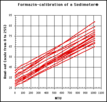
The signal level is a function of sediment concentration in the measurement zone of the detector. This graph illustrates the relationship (data by author).
Calibrations indicate that the responce is linear in the range 0 to 1000 NTU (higher concentrations have not been tested yet). As is evident from the graph - which is based on actual calibration data - the response from individual detectors in the same sensor varies. Without calibration the accuracy is not better than +-200 NTU, the resolution being 25 NTU. With calibration, the accuracy improves to about +-50 NTU.
If a specific detector is completely covered by sediments, the signal level gets close to 255. The exact level depends on the sediment characteristics, making possible the measurement of water content in soft sediments. Of course, sediment concentration in the water, or water content in the sediments, are just two sides of the same coin. The Sedimeter® can be used for both purposes, and thus measure those parameters right through the interesting sediment-water interface.
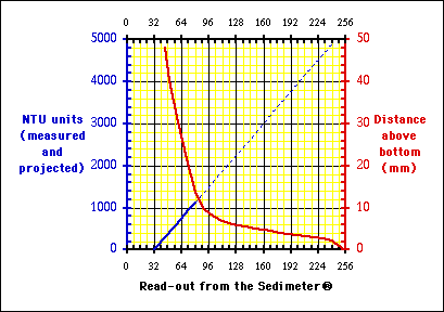
Each detector can sense sediments at a distance of several centimetres outside the tube. This means that the detectors that are close above the bottom will indicate a higher value. In the graph the red line shows how this effect decreases with distance above the bottom (those data are from Nautic Systems). Already one detector from the bottom the level is down to about 95.
The NTU calibration data from the previous graph have been averaged and plotted together with the distance data, as the blue line. Using the graph it is possible to get an idea of how big a sediment concentration must be at a certain distance above the bottom, to be clearly discernible.
This approach may be suggested for analysing the data:
1. Fit the measured values to the red "distance line" so that no measurement point falls to the left of the red line (use the part of the curve between read-outs 96 and 240, and "push" your data as high as needed to get all points above and to the right of the red line)
Future research includes to investigate the combined effect of back-scatter from the bottom, and from turbidity in the water close above the bottom (point 4 above).
The signal as a function of sediment concentration
The signal as a function of distance above the bottom
2. Identify the elevation of the bottom
3. For each point above the bottom, measure the read-out difference between the red line and your point
4. On the blue line, check what that read-out corresponds to in NTU units - this ought to give you a minimum value, but more testing remains to be done. Furthermore, wherever the sediment concentration is of interest, a calibration should be done against the actual sediment in the field area.
Observations